Kokopelli
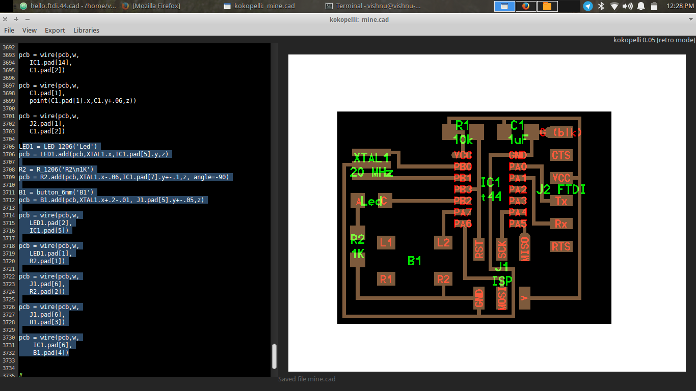
We started using Koko[eli to design circuits. For understanding easily Franc told us to download and look into the .cad file of “hello ftdi” , which we got from the Fab Academy archives. Instead of starting from scratch, we can use the library set made my Neil, we just have to create the board alone. The programming is done in Python and is quite easy to absorb and self explanatory. Fran walked us through all the steps from defining the size of the board, trace width, adding components etc till we export as .png files for milling.
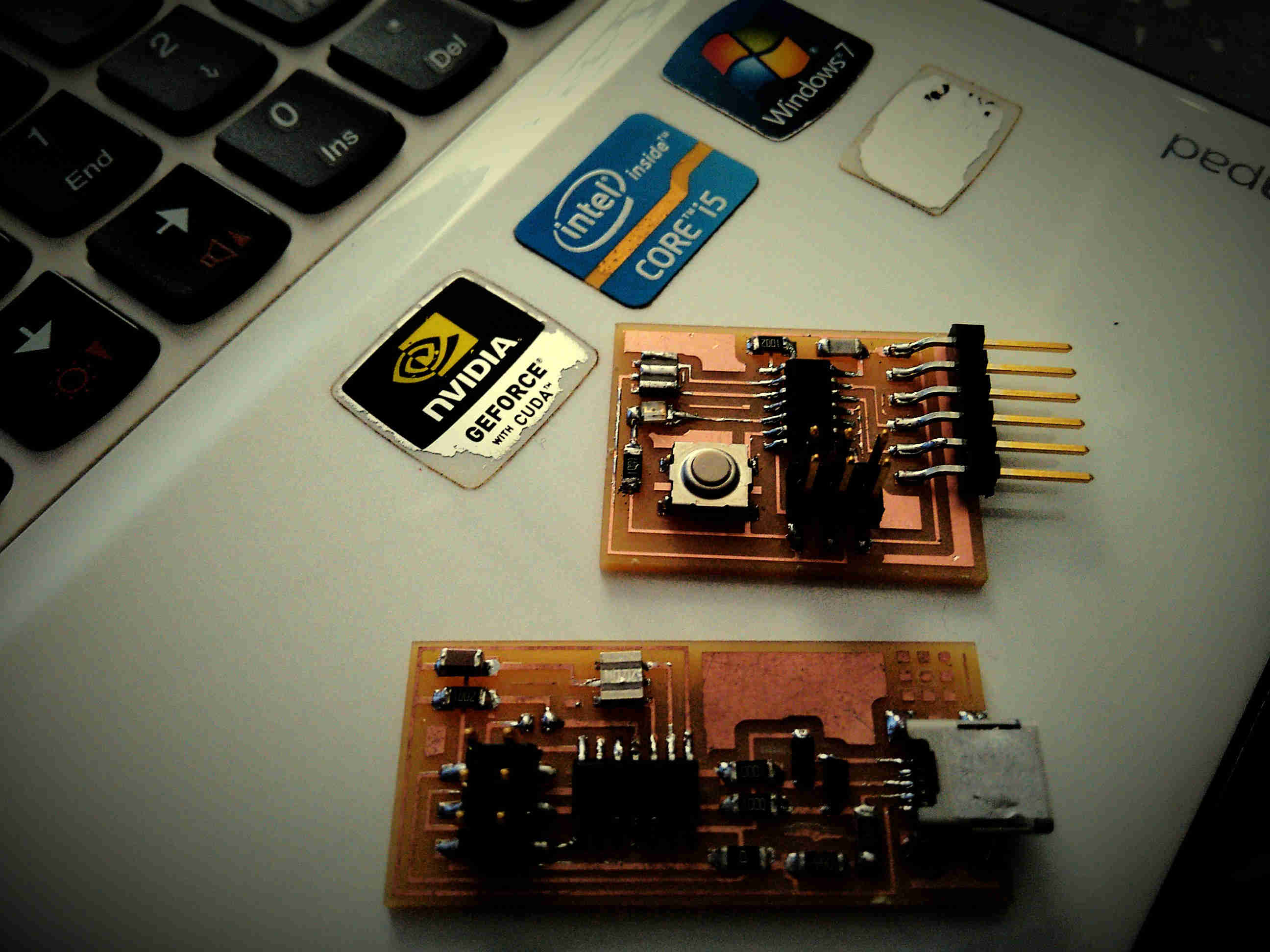
After all that we decide to modify a board and make our own version so that we can get hands on experience on designing a board. WE choose to modify the “Hello FTDI” board and add an LED and a switch. We opened the .cad file in kokopelli and added three components, a resistor,LED and a switch, using the libraries made by Neil. Franc taught us how to find the needed components from the libraries formed and how to place them on the board relating to the position of other components. This step is very similar to that in Antimony were we form shapes with respect to some basic figure. After the necessary changes were made we exported the traces and exterior files for milling. We milled them, soldered the components and formed the board.
 Code I added for the extra components
 the completed board - the one on top.